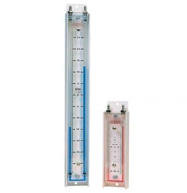
Vertical Inclined Liquid Column Manometers
Interpretation of Pressure Range and Units
Large instrument on the left:
Pressure range: from -25 to+25 millibars, with a division value of approximately 0.5 millibars.
Key pressure points: The scale values listed in the figure (such as 0.25, 0.50… 28.00) correspond to the height difference of the liquid column. The actual pressure needs to be calculated through the double tube liquid level difference (for example, if the red liquid column rises by 10.00 scales on the left and falls by 10.00 scales on the right, the differential pressure is 20.00 mbar).
Small instrument on the right:
Range estimation: A smaller range, possibly -50 to+50 Pa (approximately -0.5 to+0.5 mbar), is used for extremely high-precision micro pressure measurement.
Conversion of pressure units:
1 mbar=100 Pa=approximately 0.0145 psi
Applicable: This range is specifically designed for measuring extremely low pressures, such as ventilation systems, clean room pressure differentials, or gas flow rates.
Use pressure to generate key parameters
Parameter description:
Maximum working pressure: usually not exceeding ± 30 mbar (with a safety margin of about 20%) to avoid liquid blowing out or structural damage.
Resolution: Approximately 0.1-0.5 mbar, depending on scale division and liquid density (usually ethanol or oil-based solutions).
Accuracy level: The typical accuracy of mechanical U-tubes is ± 1% FS (full range), which is ± 0.5 mbar (for a range of 50 mbar).
Media compatibility: Only applicable to non corrosive gases (such as air, nitrogen), liquids may contaminate pipelines.
Temperature effect: Changes in ambient temperature can cause changes in liquid density. It is recommended to use within the range of 10-40 ° C, and high-temperature specialized liquids should be selected for high temperatures.
| Work scenario | Typical pressure range | Instrument selection suggestions |
| HVAC duct pressure difference monitoring | 5–20 mbar | Left instrument panel (main range) |
| Maintaining positive pressure in the clean room | 5–15 Pa(0.05–0.15 mbar) | Right small range instrument |
| Filter blockage alarm | The pressure difference increases to10–25 mbar | Left instrument panel |
| Burner inlet pressure monitoring | -5 +5 mbar | Applicable to both sides (measured in the center) |
| Negative pressure control of biosafety cabinet | -10 + -30 Pa | Right instrument (negative pressure monitoring) |
Pressure parameter selection
| Pressure range | Model | Pressure range | Model | Model | Range |
| 0-1000PA | COL 100MM | 0-100mmH2O | 0-10mbar | COL 4In | 0-4 InWG |
| 0-1500PA | COL 150MM | 0-150mmH2O | 0-15mbar | COL 6In | 0-6 InWG |
| 0-2000PA | COL 200MM | 0-200mmH2O | 0-20mbar | COL 8In | 0-8 InWG |
| 0-3000PA | COL 300MM | 0-300mmH2O | 0-30mbar | COL 12In | 0-12 InWG |
| 0-4000PA | COL 400MM | 0-400mmH2O | 0-40mbar | COL 16In | 0-16 InWG |
| 0-6000PA | COL 600MM | 0-600mmH2O | 0-60mbar | COL 24In | 0-24 InWG |
| 0-8000PA | COL 800MM | 0-800mmH2O | 0-80mbar | COL 32In | 0-32 InWG |
| 0-10000PA | COL 1000MM | 0-1000mmH2O | 0-100mbar | COL 40In | 0-40 InWG |
Precautions for use:
1.Installation direction: It must be suspended vertically to avoid reading errors caused by tilting.
2.Connection method:
The high voltage end (usually marked with “+”) is connected to the top interface, and the low voltage end (marked with “-“) is connected to the bottom interface.
When using hose connections, it is necessary to evacuate the air to avoid bubbles affecting accuracy.
3.Reading method:
Directly read the liquid level difference between the two pipes (if the left pipe rises by 12.00 and the right pipe falls by 12.00, then the differential pressure is 24.00 mbar).
If the liquid level is below zero, it is necessary to check the sealing of the pipeline or whether the liquid has evaporated.
4.Maintenance requirements:
Regularly check if the liquid color is normal (clear red blue boundary).
After long-term use, it may be necessary to replenish or replace the liquid (according to the manufacturer’s specified model).