

Core Features: High accuracy class (e.g., Class 0.4, Class 0.25), suitable for calibrating standard working pressure gauges or conducting precision measurements.
Application scenarios:
Calibration tools for on-site instrument technicians in oilfields.
Key points requiring precise measurement and accounting.
Installation steps
1. Preparation work
Confirm pressure compatibility: Ensure that the range of the pressure gauge (0-1.6 MPa) covers the maximum working pressure of the tested system, and the working pressure is recommended to be between 1/3 and 2/3 of the range for optimal accuracy and service life.
Check medium compatibility: Confirm that the internal material of the pressure gauge (usually copper alloy or stainless steel) is compatible with the measured medium (such as gas, oil, water, steam, etc.) to prevent corrosion.
Prepare tools and accessories: Prepare suitable wrenches, raw tape or gaskets, and corresponding pipe joints (which may require adapters).
2. Installation location selection
Easy to observe: Installed in a well lit and easily readable location.
Avoid vibration: Keep as far away as possible from vibration sources such as pumps and compressors, or use shock absorbers.
Avoid extreme temperatures: stay away from surfaces that are too hot or too cold, and prevent the components inside the meter from being affected by thermal expansion and contraction.
Easy to maintain: leaving sufficient operating space.
3. Connection interface
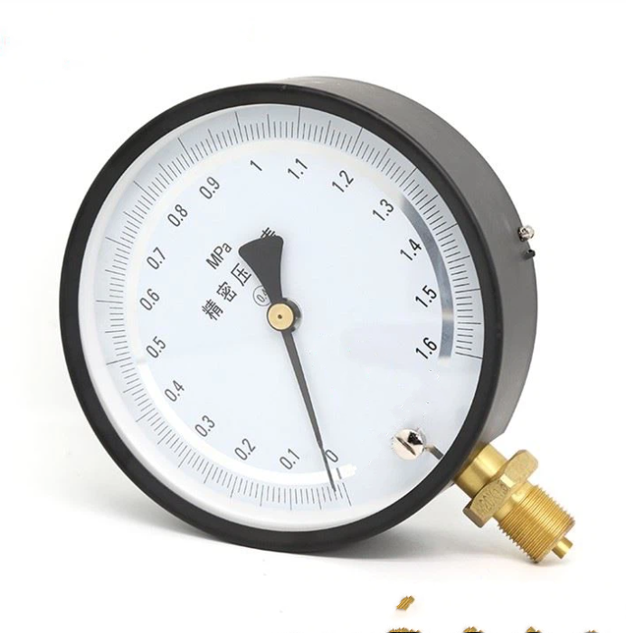
Confirm interface thread: The brass colored interface at the bottom of the pressure gauge in your photo is a standard pressure input end. Common threads are M20 × 1.5 (metric) or G1/4 (imperial). Please make sure to confirm that the interface matches the tested system.
Correct sealing:
Wrap PTFE tape (for gas or non oil media) or apply suitable sealant on the thread.
Pay attention to the winding direction (clockwise) to avoid debris entering the pipeline.
If there is a flat sealing interface, please use the matching copper gasket or rubber gasket.
Tighten the connection: First screw the joint in by hand, ensuring it is aligned with the thread, and then use a wrench to tighten it moderately. Do not apply excessive force to avoid damaging the brass interface or case.
4. System connection
If there are pulses or pressure fluctuations in the pipeline (such as near a pump or valve), it is recommended to install a needle valve or buffer (damping screw) in front of the pressure gauge to protect the internal movement of the pressure gauge.
For measuring gas pressure, especially for high-pressure gases, the valve should be opened extremely slowly.
Debugging steps
1. Check after installation
Confirm that all connections are securely fastened and leak free.
Check if the pressure gauge pointer is in the “0” position. If there is a slight deviation, it can be adjusted through calibration in the future; If the deviation is significant, it may be damaged during transportation.
2. Stress testing and readings
Slowly increase pressure: First, close the valve in front of the pressure gauge (if any), and then slowly open the valve of the tested system to allow the pressure to enter the pressure gauge smoothly.
Observing pointer:
The pointer should rise steadily without any jamming or jumping.
In the system’s no pressure state, the pointer should steadily point to the “0” position.
Apply pressure to the commonly used working pressure point and observe if the indication is stable.
Full range test (if necessary): Under safety conditions, slowly increase the pressure to the upper limit of the range (1.6 MPa), check if the pointer points accurately to the full scale, then slowly release the pressure back to zero and observe if the pointer returns to zero. This operation should be avoided frequently.
3. Sealing test
After increasing the pressure to the working pressure of the system, close the valve in front of the pressure gauge and maintain it for a period of time.
Observe whether the pointer has a slow downward trend. If there is, it indicates that there may be a leak at the connection and needs to be checked and resealed.
4. Calibration comparison (when high precision is required)
For precision measurement, a higher-level standard pressure source (such as a digital pressure calibrator) should be used for comparison after installation.
Record the difference between the pressure gauge reading and the standard value at several key points (such as 0.4 MPa, 0.8 MPa, 1.2 MPa) to determine whether it meets the accuracy level (such as 0.4 level) requirements.
Application
1. Core industries and process control fields
Petrochemical and Natural Gas
Application: Monitor the process pressure of pipelines, reactors, storage tanks, compressors, and separators.
Function: Ensure the stability and safety of the production process, prevent danger or quality fluctuations caused by overpressure or insufficient pressure.
power industry
Application: Used for pressure monitoring of boilers, steam pipelines, steam turbine systems, and water pressure systems.
Function: To ensure the safe and efficient operation of power generation equipment, it is a key safety monitoring instrument for thermal power systems.
Mechanical Manufacturing and Hydraulic/Pneumatic Systems
Application: Installed on hydraulic stations, pneumatic circuits, test benches, injection molding machines, machine tools, and other equipment.
Function: Directly display system working pressure, used for equipment debugging, performance testing, and daily maintenance.
Metallurgy and Mining
Application: Pressure monitoring of blast furnace, rolling mill hydraulic system, air compressor, ventilation system, and mine drainage system.
Function: Provide stable and durable pressure indication in harsh industrial environments.
2、 Precision manufacturing and quality inspection field
Pharmaceutical and Bioengineering
Application: Fermentation tanks, sterilization cabinets, purified water systems, and pipeline pressure monitoring in clean workshops.
Function: Compliant with GMP standards, ensuring precise and controllable process parameters in the production environment.
Food and beverage processing
Application: Pressure control points for sterilization pots, filling machines, homogenizers, CIP cleaning systems.
Function: To ensure food safety and consistency in processing technology.
Semiconductors and specialty gases
Application: Pressure indication for high-purity gas transmission pipelines and special gas cabinets (compatible material instruments are required).
Function: To prevent pollution and precisely control the supply of pressure sensitive gases.
3、 Research, Calibration, and Service Fields
Laboratories and research institutions
Application: As a working standard, used for comparing and calibrating ordinary pressure gauges; Or install it on experimental devices (such as fluid mechanics and thermodynamics experimental platforms) for data collection.
Function: Provides real-time pressure feedback that is more intuitive and delay free than digital instruments, and does not require power supply.
Measurement and equipment calibration services
Application: As a transmission standard, it is used within the enterprise or in third-party calibration laboratories.
Function: Establish a traceable pressure measurement system to ensure the accuracy of instruments throughout the factory.
Equipment maintenance and installation debugging
Application: carried by technicians, used for diagnosing system faults, debugging new equipment, or acceptance after installation.
Function: Portable and reliable, it is a practical tool for on-site work.
FAQ:
1. Question: What type of pressure gauge is this?
Answer: This is a precision mechanical pointer pressure gauge. The clear words “precision pressure” on the dial indicate that its design and manufacturing accuracy is much higher than that of ordinary industrial pressure gauges, and it is usually used in situations that require high-precision monitoring or comparison as a working standard.
2. Question: What is its measurement range and units?
Answer: The measurement range is from 0 to 1.6 MPa. The pressure unit adopts the internationally recognized MPa (megapascal). This is the maximum pressure limit that it can safely and accurately measure.
3. Question: What is its accuracy level?
Answer: It usually belongs to instruments with 0.4, 0.25 or higher precision. The specific level needs to be referred to the product nameplate or manual, and the maximum allowable error is ± 0.4%, ± 0.25% or less of the full range (1.6MPa).
4. Question: What media can it measure?
Answer: It can measure gas or liquid media that are non corrosive to brass, copper alloys, and internal movements, such as air, nitrogen, water, hydraulic oil, etc. When measuring corrosive, flammable, explosive, or high-temperature media, it is necessary to confirm whether the instrument material is specially customized or equipped with isolation devices.
5. Question: How to read the pressure value?
Answer: Observe the scale value corresponding to the tip of the stationary black pointer on the dial. This dial has two circles of graduations, with the inner circle having subdivided graduations for precise reading. The pointer in the picture is pointing towards a position close to “0”.
6. Question: What are the advantages of this high-precision pressure gauge?
Answer: Compared with ordinary pressure gauges, its main advantages are high precision, high stability, and good repeatability. Compared with digital pressure gauges, its advantages are no need for power supply, resistance to electromagnetic interference, intuitive and reliable, and simple maintenance.
7. Question: What should be noted during installation?
Answer: Key considerations include:
Correct selection: Ensure that the range (1.6MPa) covers the working pressure and the medium is compatible.
Thread matching: Confirm that the thread specifications of the golden interface are consistent with the system interface.
Reliable sealing: Raw material tape or gasket should be used during installation to ensure no leakage.
Avoid overload: It is strictly prohibited to exceed a pressure of 1.6MPa. If the pressure is increased, the action should be gentle.
Common standard pressure range for precision pressure gauges (taking gauge pressure as an example)
The range of a pressure gauge usually follows a standardized sequence (such as R5, R10 priority number system), and the following are some of the most common ranges (unit: MPa, 1 MPa ≈ 10 kgf/cm ²):
1. Micro pressure and low pressure (commonly used for ventilation, environmental monitoring, burner pressure, etc.)
0 ~ 0.1 kPa, 0 ~ 0.25 kPa, 0 ~ 0.4 kPa
0 ~ 1 kPa, 0 ~ 2.5 kPa, 0 ~ 4 kPa, 0 ~ 6 kPa, 0 ~ 10 kPa
2. Medium and low pressure (most common range, suitable for pneumatic systems, water pressure, general process control)
0 ~ 0.01 MPa, 0 ~ 0.016 MPa, 0 ~ 0.025 MPa, 0 ~ 0.04 MPa, 0 ~ 0.06 MPa
0 ~ 0.1 MPa, 0 ~ 0.16 MPa, 0 ~ 0.25 MPa, 0 ~ 0.4 MPa, 0 ~ 0.6 MPa
3. Medium and high pressure (widely used in hydraulic systems, pumps, compressors, and pipeline pressure)
0 ~ 1.0 MPa, 0 ~ 1.6 MPa, 0 ~ 2.5 MPa, 0 ~ 4.0 MPa, 0 ~ 6.0 MPa, 0 ~ 10 MPa
4. High pressure and ultra-high pressure (used for high-pressure cleaning, petrochemicals, material testing, and ultra-high pressure processes)
0 ~ 16 MPa, 0 ~ 25 MPa, 0 ~ 40 MPa, 0 ~ 60 MPa, 0 ~ 100 MPa
0~160 MPa, 0~250 MPa or even higher
If there are other pressure options, please contact DERKIA official sales@derkia.com for purchase.