
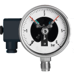
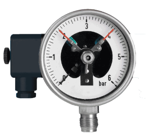
Electric contact pressure gauge
Core Features:
The device is equipped with an electrical contact mechanism on the basis of a pressure gauge. When the pressure reaches the preset upper or lower limit, it connects or disconnects the control circuit, enabling automatic alarm or interlock control.
Application scenario:
Automatic start-stop control of the compressor.
Pressure and pressure vessel overpressure alarms and safety interlocks.
Dry run protection for the pump.
Different pressure selection of electric contact pressure gauge:
| Application | Pressure range |
| 1. Hydraulic and Pneumatic Systems | Conventional range: 0-300 bar (high-pressure hydraulic) or 0-16 bar (low-pressure pneumatic) |
| 2. Air conditioning refrigeration system | Conventional range: Refrigerant pressure varies by type (R410A high pressure can reach over 40 bar, R134a low) |
| 3. Water treatment and supply system | Conventional range: 0-25 bar (municipal water supply pressure is usually below 10 bar). |
| 4.Industrial process control | Conventional range: extremely wide, from vacuum to hundreds of bars. |
For the most typical application of 0-6 bar range electric contact pressure gauges:
| Item. | Application | Specific application |
| Electric contact pressure gauge with a range of 0-6 bar | 1.Hydraulic and Pneumatic Systems | Low pressure pneumatic control system: used for monitoring and controlling the air source pressure of factory automation equipment, pneumatic fixtures, material conveying, etc. (usually working pressure between 4-7 bar). Low pressure hydraulic auxiliary system: such as certain lubrication systems, coolant circulation systems, or lightweight hydraulic clamping devices. Key point: Not applicable to medium and high pressure hydraulic systems such as main hydraulic cylinders and injection molding machines“ |
| 2.Air conditioning refrigeration system | Pressure monitoring of chilled water/cooling water system: used for controlling the inlet and outlet pressure of chilled water pumps and cooling water pumps in central air conditioning to prevent low pressure caused by water shortage or filter blockage. Air side pressure monitoring: such as static pressure control of air supply ducts. Key point: Not suitable for directly measuring the pressure on the high-pressure or low-pressure side of the refrigerant (usually requires a dedicated refrigerant gauge with a higher range or a composite vacuum pressure gauge). “ |
|
| 3. Water treatment and supply system | Building constant pressure water supply: Monitor the pressure of the pipeline network, control the start and stop of the variable frequency pump, and maintain the set pressure (such as 2-4 bar). Water tank/water tower level control (indirectly measured through pressure). Pre treatment stage of reverse osmosis (RO) system: monitoring the pressure of raw water and the pressure difference of the security filter. Pressure control of irrigation system. “ |
|
| 4.Industrial process control“ | Boiler auxiliary system: Monitor blower air pressure, fuel/air pressure (low-pressure burner), and soft water system pressure. Air compressor post-treatment equipment: Monitor the pressure difference before and after the dryer and filter (differential pressure gauge is required, but the principle is the same). Chemical and food and beverage industries: inert gas (such as nitrogen) covering pressure protection for various reaction vessels and tanks, and pressure monitoring for conveying pipelines. Key point: Suitable for monitoring process gas sources, protective gases, low-pressure reaction vessels, and fluid transport, rather than high-pressure processes in the main reactor. “ |
|
| Summarize | The most core and typical application areas of electric contact pressure gauges with a range of 0-6 bar are: Low pressure pneumatic control system (factory automation). Building water supply and constant pressure control system. Pressure control of the water system in central air conditioning. Auxiliary gas pressure monitoring and interlock protection in industrial processes. |
FAQ:
Q1:What is this product?
A: This is an electric contact pressure gauge, it is also known as a pressure gauge with contact signals. It can not only display pressure intuitively through the pointer like a regular pressure gauge, but also trigger switch signals through internal electrical contacts for automatic control or alarm when the pressure reaches the preset value.
Q2:What is the measurement range? What is the unit?
A2:The dial displays a measurement range of -1 to 6 bar. The unit is bar, and 1 bar is approximately equal to 0.987 standard atmospheric pressure or 100 kilopascals (kPa). Note: The range includes the negative pressure (vacuum) part, indicating that this meter can also be used to measure micro negative pressure systems.
Q3:Why is the pointer red green dual color? What do they represent respectively?
A3:In an electric contact pressure gauge, the red green dual color pointer is usually not a fixed setting needle, but rather:
Black (or single color) main pointer: indicates the current actual pressure value.
Adjustable setting pointers: There are usually 1-2 independent pointers on the dial that can be adjusted through external knobs (not directly shown in the figure, may be below the main pointer or transparent/different colors), used to set the upper or lower pressure limit. When the main pointer coincides with the set pointer, an electrical signal is triggered.
The possible meaning of the red green dual color main pointer: In some designs, the dual color pointer itself may be used for quick visual prompts (e.g. green area indicates safety, entering the red area indicates approaching the upper limit), but its core control function is still completed by independent adjustable setpoints. Please refer to the product manual to confirm its design logic.
Q4:What is the specification of the metal interface at the bottom?
A4:This is a pressure interface used to connect to the pipeline or equipment being measured for pressure. Common specifications include metric or imperial threads such as G1/4, G1/2, M20 * 1.5, etc. Users must select based on the interface size of their system, which is usually engraved near the interface or on the nameplate.
Q5:What is the black component on the left? What is its function?
A5:That’s a junction box. Internally equipped with electrical contact switches and wiring terminals. Users can connect control circuits (such as PLC, relays, or alarm lights) through it. When the pressure reaches the set value, the internal switch will activate to turn on and off the circuit, thereby achieving automatic control (such as starting/stopping the water pump) or issuing an alarm signal.
Q6:What are the small numbers (3, 1, 5, 2, 4, 3, 6) on the dial?
A6:These are the numerical identifiers corresponding to the main scale lines. The scale of a pressure gauge is usually divided into a main scale (long line, marked number) and a secondary scale (short line). The numerical sequence here is: 0, 1, 2, 3, 4, 5, 6 (corresponding to the main scale), and -1. The “3,1,5,2,4,3,6” you listed may be a partial description of the position of the scale line. ‘bar’ is a unit of pressure.
Q7:What applications can this instrument be used for?
A7:Suitable for medium and low pressure systems that require pressure monitoring and automatic interlocking, such as:
1. Pneumatic control system: Air source pressure control for factory automation equipment (commonly 4-7 bar).
2. Water supply system: Constant pressure water supply for buildings, controlling the start and stop of water pumps.
3. Air conditioning system: pressure protection for chilled water/cooling water circulation.
4. Industrial process: Tank gas pressure maintenance, fluid transmission pipeline pressure monitoring.
Q8:Does it require power supply? How to connect the wires?
A8:The mechanical indication part of the pressure gauge does not require power supply.
The electrical contact switch part needs to be connected to the control circuit. There are usually three terminals inside a junction box: a common point, a normally open contact, and a normally closed contact (subject to physical labeling). Users need to connect the circuit according to the control logic (whether to alarm when the pressure is high or low) and provide it with a working voltage (commonly such as 24VDC or 220VAC).
Q9. How to set the control pressure point?
A8:There are usually one or two rotatable knobs or levers on the edge or shell of the dial, used to independently adjust the position of the setting pointer. For example, if the setting needle is rotated to 5 bar, the electric contact will activate when the main pointer rises to 5 bar. Please make sure to understand the safe pressure range of the device before setting it up.
Q10:What are the precautions for selection and use?
1. Range selection: The optimal working pressure should be between 1/3 and 2/3 of the range, and the operating condition of 4 bar shown in the figure is suitable.
2. Medium compatibility: Ensure that the internal materials of the instrument (such as Bourdon tubes, seals) can withstand the tested medium (air, water, oil, etc.).
3. Accuracy level: commonly 1.6, indicating a maximum allowable error of ± 1.6% of the measurement range.
4. Protection level: If used in humid or dusty environments, products with appropriate protection levels (such as IP65) should be selected.
5. Regular calibration: To ensure accurate and reliable control, it is recommended to have professional personnel calibrate periodically.