


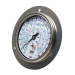
HVAC Pressure Gauge type MFG with flange Features
- Range High: -1/+38 bar 14,50/500 psi
- Range Low: -1/+18 bar 14,50/260 psi
- Case Material: AISI 304 stainless steel
- Window: plexiglass
- Socket: 1/4 SAE or 1/8 NPT, bottom, OT 58 brass
- Elastic element: phosphor bronze
- Movement: gearing, OT 59 brass
- Dial: white
- Pointer: black oxidized aluminium
- Accuracy: cl. 1,6
- Ambient-T: +15 / +65°C / +59/149 °F
- Process fluid-T: max. +65°C / +149 °F
- Process pressure: max. 75% of full scale value
- Over pressure: 25% of full scale value
- Protection: IP65 according IEC29
- Over pressure: 25% of full scale value
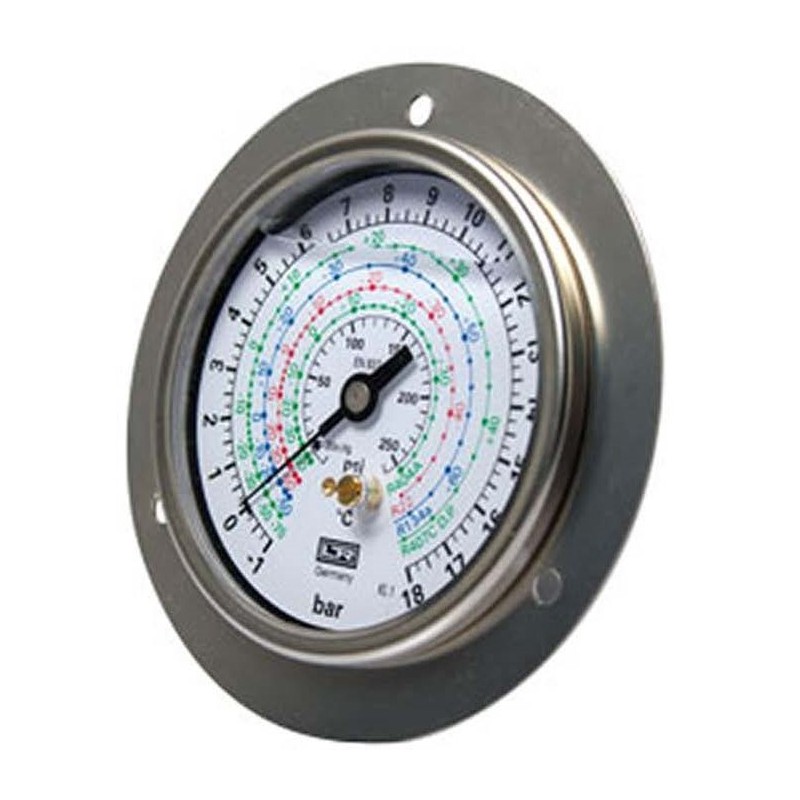
HVAC Pressure Gauge type MF Options
- Diameter: 63, 80 or 100
- Connection Size and Location: ¼” SAE, 1⁄8” NPT, Location Bottom or Back
How to use this pressure gauge:
1. System connection
Red hose: Connect the high-pressure interface of the pressure gauge (usually marked as “HI” or “HIGH”, or only marked in red), and connect the other end to the high-pressure side of the compressor (i.e. the exhaust pipe or corresponding maintenance valve).
Blue hose: Connect the low-pressure interface of the pressure gauge (usually marked as “LO” or “LOW”, or only marked in blue), and connect the other end to the low-pressure side of the compressor (i.e. the return pipe or corresponding maintenance valve).
Yellow (or middle) hose: Connect the middle/common interface of the pressure gauge, with the other end depending on the working stage, and then connect to the vacuum pump or refrigerant cylinder.
Preparation before operation: Before connecting, ensure that the pressure gauge and all valves are closed (tighten the handwheel on the manifold counterclockwise).
2. Core workflow:
A. Vacuum pumping
This is a necessary step before filling the refrigerant after installation or maintenance, with the aim of removing air and moisture from the system.
Connection: Connect the yellow hose to the inlet of the vacuum pump.
Operation: First turn on the vacuum pump, then slowly open the high and low pressure valves on the pressure gauge manifold. At this point, the pointers of both meters will begin to move towards negative pressure.
Monitoring unit:
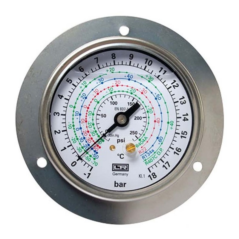
On the left side of the innermost circle (black scale) of the dial, negative values (-20, -30…) starting from “0” to the left are measured in inches of mercury (inches of mercury), which is the vacuum degree.
The goal of vacuuming is to stabilize the low pressure gauge pointer at least -29.5 in. Hg (i.e. close to -30 in. Hg, corresponding to a vacuum degree of approximately 0.5 millimeters of mercury or 500 micrometers of mercury), and maintain it for at least 15-30 minutes to ensure that there is no pressure rebound.
End: First, close the high and low pressure valves, and then turn off the vacuum pump.
B. Leak detection
Check after vacuuming, before filling, or when the system is not working.
Static pressure holding method:
After completing the vacuum pumping, close all valves and let it stand for several hours (usually 15-30 minutes to make a preliminary judgment).
Observing the pressure gauge: If the pointer of the high and low pressure gauges rises from the negative pressure position towards zero or positive pressure, it indicates that there is a leak in the system.
Pressure leak detection method:
A small amount of nitrogen (dry, moisture free) can be added to the system to create positive pressure, and the pressure gauge can be observed to see if it drops.
C. Filling refrigerant:
This is the process of replenishing or refilling refrigerant in the system.
Connect to the outlet of the refrigerant cylinder:
Disconnect the yellow hose from the vacuum pump and connect it to the outlet of the refrigerant cylinder.
If it is the first time to charge a new system, it is usually slowly charged in gaseous form from the low-pressure side.
If it is a supplementary refrigerant, it can be charged from the high-pressure side (liquid) or low-pressure side (gas) according to the situation.
Operation and monitoring (taking low-pressure side gaseous charging as an example):
Slightly open the refrigerant cylinder valve and exhaust the air from the hose (“exhaust” operation).
Open the low-pressure valve (corresponding to the blue interface) of the pressure gauge, and keep the high-pressure valve closed.
Start the air conditioning/cooling system and operate it in cooling mode.
Observe the low pressure gauge:
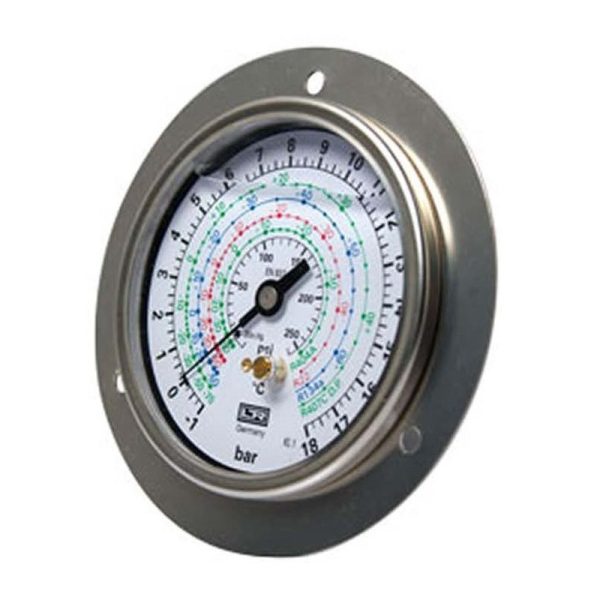
Read pressure: Look at the black scale on the inner ring, in psi (such as 1, 5, 10, 15… on the inner ring in your picture).
Reading temperature: This is the core function of this meter. Find the current psi value pointed to by the low pressure gauge pointer, and then look horizontally outward to correspond to the scale on the outer ring of the dial that is the same color as the refrigerant used in the system. For example, if the system uses R404A, look at the temperature scale (-50 ° C to+50 ° C) corresponding to R404A (which may be circled in blue or green in the picture), and this temperature is the evaporation saturation temperature of the refrigerant at the current pressure
3. Parameter determination:
Compare the read saturation temperature with the inlet temperature of the evaporator. The temperature difference (superheat) between the two is a key parameter for determining whether the filling amount is appropriate. Adjust the filling amount according to the design superheat of the system until the optimal value is reached.
FAQ
1. Q: What type of instrument is this? What is the main purpose?
A: This is a composite manifold pressure gauge, also known as a pressure temperature gauge. It is mainly used for the installation, maintenance, leak detection, vacuuming, and refrigerant charging of refrigeration, air conditioning (HVAC), and heat pump systems.
2. Q: What is the relationship between the black scale (psi/bar) on the innermost ring and the colored scale (° C) on the outer ring of the dial?
A: The inner circle scale (psi and bar) indicates the system pressure. The temperature scale (° C) corresponding to different colors on the outer ring represents the saturation temperature of a specific refrigerant at that pressure. For example, when the low pressure gauge pointer points to 40 psi, the saturation temperature corresponding to R404A (assumed to be the blue circle) is about -10 ° C. This can help technicians quickly determine the system status without consulting the pressure temperature comparison table.
3. Q: How to read the vacuum degree?
A: Check the negative pressure scale on the left side of the dial. The black scale on the inner ring of the low pressure gauge in the picture extends from “0” to the left and is marked with “in. Hg” (inches of mercury), for example -20, -30. This is used to measure vacuum degree. When vacuuming, the pointer will point to that area.
5. Q: What refrigerants can it measure?
A: According to the multi-color outer ring scale, it is usually compatible with various common refrigerants such as R22, R134a, R404A, R407C, etc. Each color corresponds to the saturation temperature of a refrigerant. When using, it is necessary to read the temperature scale of the corresponding color according to the actual refrigerant type filled in the system.
6. Q: How to use this meter for vacuuming operation?
A: 1) Connect the red and blue hoses of the meter to the high and low pressure maintenance valves of the system respectively; 2) Connect the central yellow tube to the vacuum pump; 3) Open the high and low pressure valves on the pressure gauge and start the vacuum pump; 4) Observe the low pressure gauge pointer until it stabilizes at -29.5 in. Hg or lower (high vacuum state), and hold for a period of time to confirm that the system is leak free and moisture has been removed.
7. Q: How to use it to determine if the refrigerant charge is appropriate?
A: During system operation, read the low-pressure gauge pressure and its corresponding refrigerant saturation temperature (e.g. R404A corresponds to -10 ° C). Subtract the saturation temperature from the actual temperature at the inlet of the evaporator to obtain the degree of superheat. By adjusting the refrigerant charging amount, the degree of superheat reaches the system design value (usually 4-8 ° C), which is considered appropriate charging.
8. Q: What is the difference in use between a high voltage gauge (red background/area) and a low voltage gauge (blue background/area)?
A: Low pressure gauge: mainly used to monitor the low pressure and low temperature on the evaporator side, it is the main observation gauge for vacuum pumping and refrigerant filling. *High pressure gauge: mainly used to monitor the high pressure and high temperature on the condenser side, to check whether the system high pressure is normal, and to prevent excessive condensation pressure.
9.Q:This pressure gauge cannot be excluded from the applicable field (warning)
A:Not suitable for high temperature steam, corrosive chemicals, high viscosity fluids (such as hydraulic oil), or flammable and explosive gases (unless the instrument has special explosion-proof certification).
The “filling fluid” (usually glycerin) and elastic sealing elements inside the instrument may be corroded or dissolved by certain chemical media.
The “temperature” reading is essentially the “saturation temperature” of a specific refrigerant. For other media, this temperature scale has no direct physical meaning and can only refer to pressure values.
10. Q: What are the precautions for daily use and maintenance?
A: Pre use check: Ensure that the pointer is reset to zero and there is no jamming.
Handle with care: Avoid severe vibrations or impacts to prevent damage to the internal movement.
Keep clean: prevent dust and oil from entering the interface.
Correct connection: Ensure that the valve is closed before connecting the hose to prevent refrigerant splashing.
Regular calibration: For professional purposes, it is recommended to regularly (such as annually) send it to a professional institution for calibration to ensure accurate readings.